BoomBay 525 and Case
Stereo Speakers for mounting in a 5.25" drive bay
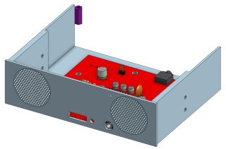
A stereo speaker and amplifier for mounting in a 5.25" computer drive bay. Intended for retro-computers but could easily be used in a modern computer.
Features
- 3D printable 5.25" mounting case
- 2 x 36mm speakers
- Powered by a standard “hard drive” style molex connector
- Connects to your sound card’s audio out
- Front volume control
- Front headphone jack socket
- Power LED
Links
BOM (THT)
| Qty | Component |
|---|---|
| 2 | 1nF Mylar/Film Capacitors |
| 2 | 150nF Mylar/Film Capacitors |
| 5 | 100uF Electrolytic Capacitors |
| 2 | 2.2uF Electrolytic Capacitors |
| 2 | 470uF Electrolytic Capacitors |
| 1 | 1000uF Electrolytic Capacitor |
| 1 | 100nf Ceramic Capacitor |
| 2 | 10KΩ Axial Resistors |
| 2 | 3.9KΩ Axial Resistors |
| 2 | 620Ω Axial Resistors |
| 1 | 680Ω Axial Resistor |
| 1 | 3mm LED |
| 2 | 5-pin 3.5mm Audio Jack Sockets TN/T/RN/R/S |
| 1 | Male “Molex” connector (see BOM notes) |
| 1 | 5-pin 10KΩ 16mm Thumbwheel Rotary Gear Potentiometer (see BOM notes) |
| 1 | TEA2025B 16pin DIP (or compatible) |
| 2 | 36mm 8Ω Speakers (range 0.25 to 1 watt) |
| 3 | 2pin Headers (2.54mm Pitch) (see BOM notes) |
| 1 | 1 x Audio Cable with 3.5mm jacks at each end |
- “Molex” Connector
- The colloquilly named Molex connector is used for power. This connector is known by many names (eg MATE-N-LOK 350211), but is essentially the same power connector that was used on older hard disks and CD/DVD drives etc.
- The right-angled version of the Molex connector would be preferred, but straight versions are perfectly usable and easier to obtain.
- The Molex connector is not required, if you intend to power the device by the alternate dupont connector instead.
- The Thumbwheel
- This is used for volume control and these components were common on many audio devices.
- It goes by various names, but ensure you get the 5pin variant with 16mm diameter gear.
- 2pin Headers
- The connector at J3 is intended for connecting a power source using a dupont connector. It is not required, if you intend to power the device by the molex connector instead.
- The connectors at J2 and J4 are intended for connecting the speakers via dupont connectors. They are not required if you intend to solder the speaker wires directly to the PCB.
- IC sockets optional.
- The thumbwheel should be mounted on the top-side of the PCB
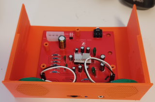
- The LED should be bent over and mounted so that the ‘bulb’ hangs just over the PCB. See the images for more context.
- Although the connection polarity of the speakers doesn’t matter electrically, it does matter acoustically. Ensure both speakers use the same connection order for their wires.